
A member of the Beimdick Group+49 (0)231 5175-0info@hstech.de

IPS-20 — Test & Simulation

Observe and simulate electrical signals.

IPS-20 simulates the process interface of substation control systems. You set indications, commands and measured values and observe the response, without connecting the real process.

Windows 11-style visualization
IPS-20 test and simulation system in a test cabinet

Application

Test without connecting the process.

IPS-20 is a multifunctional test and simulation system. In power supply, it is used for example to test bay units of substation control systems. Its freely configurable inputs and outputs also suit automation applications, such as checking control cabinets for correct wiring.

The system includes two programs: the Console for configuring, operating and observing process signals, and the Cockpit as a simplified user interface for testing. Ready-made project and layout files are supplied for a range of test scenarios.

The software

A look at Console and Cockpit.

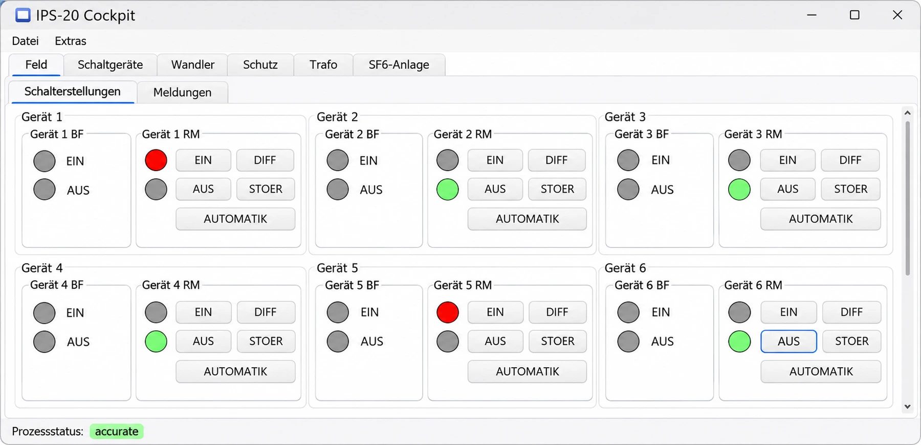
IPS-20 Cockpit showing switch positions of several devices
IPS-20 Cockpit showing switch positions of several devicesWindows 11-style visualization

Cockpit: the interface for testing

In the Cockpit you control and observe process signals, organised for example by bay, switching devices, instrument transformers and protection. No configuration takes place here: the Cockpit is designed for work during the test.

Layouts are described in XAML and can be adapted to your installation without rebuilding the software.
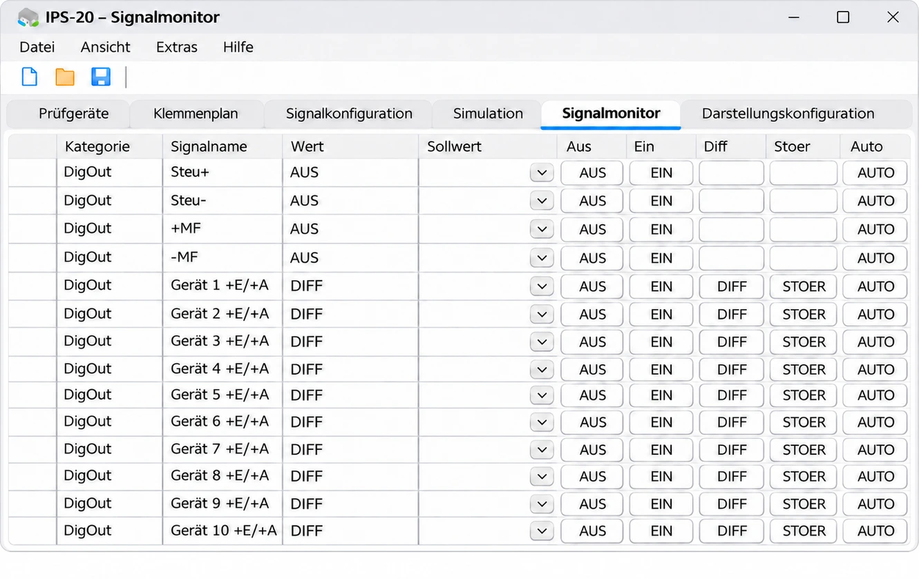
Signal monitor in the IPS-20 Console
Signal monitor in the IPS-20 ConsoleWindows 11-style visualization

Signal monitor: see and set states

The signal monitor is the main working view during a test. It shows the current state of every signal. You set values using buttons or as numbers; “Auto” hands the signal back to the simulation or the process.

  • Single signals with ON/OFF, optionally as closed-circuit signals
  • Double signals with ON, OFF, intermediate and fault position
  • Transformer tap signals as BCD-coded steps
  • Analogue signals via 0–10 V or 0–20 mA, freely scalable
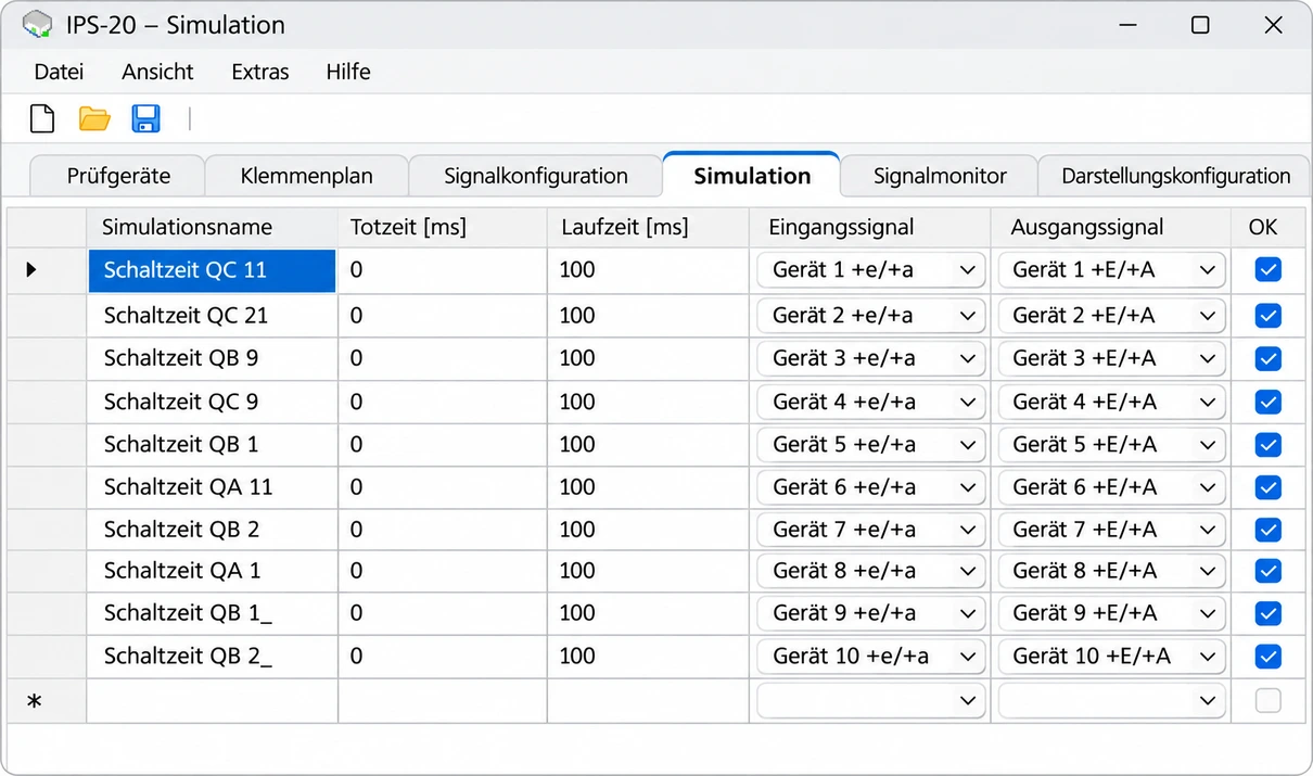
Simulations in the IPS-20 Console
Simulations in the IPS-20 ConsoleWindows 11-style visualization

Simulations: reproduce switching devices

Simulations link commands and feedback. The position indication of a switching device follows the command with adjustable dead time and travel time, including the intermediate position.

Simulations run directly on the IPS-20 hardware and therefore have defined timing.

More functions

What else IPS-20 offers.

SCL import

An SCL file according to IEC 61850-6 generates most of the IPS-20 configuration automatically.

Logic and sequences

AND/OR logic as well as circuit breaker and tap changer simulation reproduce more complex sequences.

Voltage groups

Signals can be assigned to virtual voltages. When a voltage is switched off, all assigned signals take on that state.

Your own names

Terminals and signals take names from your installation, such as the pin assignment of the process connector. Views also act as filters.

Log

Switching operations and incoming indications are recorded with time stamps.

Multiple test devices

The Console finds all IPS-20 devices on the network and uses them together in one project.

At a glance

Key facts.

Combined with CVT, electrical signals and communication tests come together in one system test.

Software
Console and Cockpit
Signal types
Single, double, tap and analogue signals
Analogue signals
0–10 V / 0–20 mA
Data basis
SCL according to IEC 61850-6
Connection
Ethernet

Your next step

Discuss IPS-20 for your application.

Tell us about your installation and requirements.

External content

Fonts, images and the location map are stored on our own webspace. External websites such as Google Maps, Xing and the careers website open only when you follow their links.